Engineering a Multi-Purpose Aerospace Facility for R&D, Production, and MRO
When a major manufacturer required a highly specialized aerospace facility for R&D and production, they needed a partner capable of managing immense technical interdependencies. ACS delivered a turnkey solution, utilizing our proven aerospace project management to coordinate a multi-firm team of specialists. By focusing on the core requirements of a turbofan engine test, we ensured that every structural and mechanical system was optimized for precision, safety, and long-term operational efficiency.
The Challenge
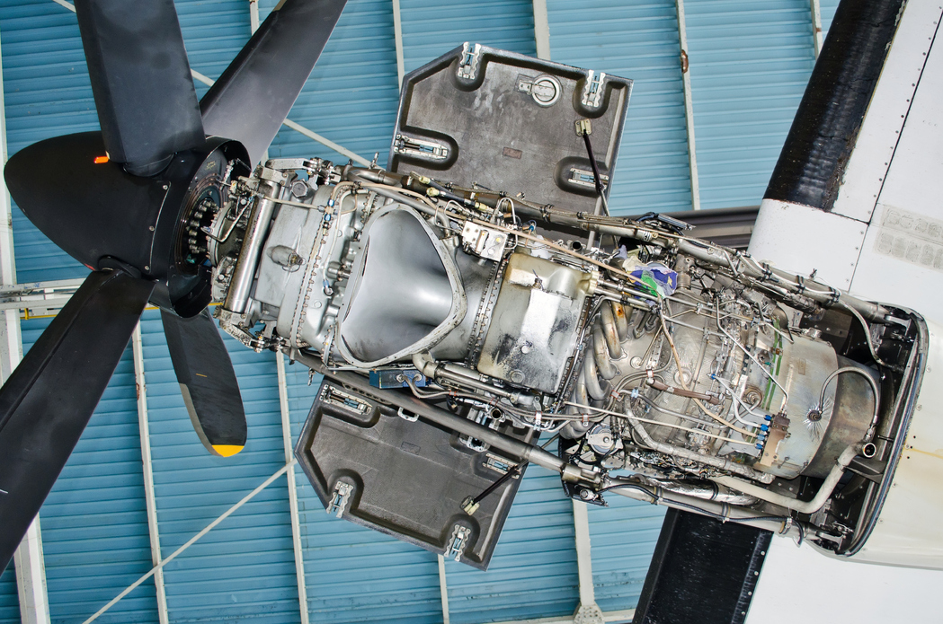
A major aerospace manufacturer needed a complete design for a turbofan engine test facility at an existing site. The aerospace facility needed to be multi-purpose, conducting R&D, production testing, and Maintenance, Repair, and Overhaul (MRO) services for turbofan engines in a variety of sizes.
The technical scope presented significant integration challenges. This multi-use requirement created competing design demands and unusual complexity. Unlike typical industrial facilities where equipment placement offers flexibility, the test cell itself functions as precision testing equipment. The building’s geometry, internal airflow, and structural characteristics directly impact testing accuracy and engine safety.
The fundamental challenge lay in the integration requirements. Success required coordinating specialists in Computational Fluid Dynamics (CFD) and aeroacoustics, structural engineering, precision force measurement systems, high-temperature/high-pressure mechanical systems, and specialized construction sequencing. As a change to one system would have a ripple effect on the others, their interdependency required a single-source contract holder with superior aerospace project management skills to manage precise cross-discipline integration and execute turnkey delivery.
The aerospace manufacturer turned to ACS due to the strong aerospace project management capabilities that the ACS team demonstrated on a previous project with the company. The client specifically valued ACS’ ability to integrate complex technical work across multiple disciplines while maintaining single-point accountability.
The Solution
ACS served as the prime contractor with full responsibility for coordinating all disciplines and subcontractors. The team included a CFD and aeroacoustics partner, an architectural and structural engineering firm, force measurement specialists, and lift platform vendors, while ACS provided the design and integration of the engine support and facility systems.
Project Governance and Stakeholder Coordination
ACS took a coordinated approach centered on intensive, structured communication. Standing weekly client meetings established design direction and forced critical path decisions. Weekly internal meetings with all partners kept disciplines aligned, while several technical breakout sessions each week addressed specific integration challenges, including:
- CFD analysis revealed small areas of concern in the test cell where equipment could potentially create airflow disruptions, causing pressure distortions at the engine inlet, risking poor engine performance or damage. ACS coordinated between structural and equipment engineers and aeroacoustics specialists to eliminate certain features and redesign appropriately while maintaining airflow quality and test cell usability.
- R&D instrumentation requirements competed with space and airflow constraints on the mezzanine walkway. ACS coordinated iterative CFD checks with evolving client needs and recommended remote I/O to reduce cabinet and cabling footprint without sacrificing testing capability.
Engine Support and Facility Systems Design
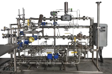
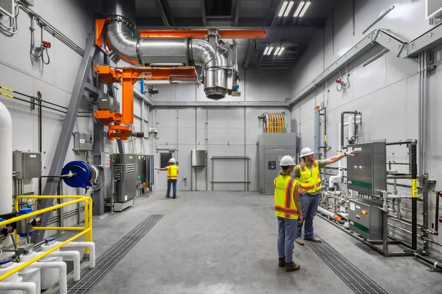
ACS led the technical design of the engine support and facility systems required for test cell operations. The team engineered the engine lube oil fill system and the more complex preservation oil system, which allows the manufacturer to flush the fuel system with preservation oil while the engine runs, protecting high‑value hardware during shipment and storage.
ACS also designed the high‑temperature/high‑pressure bleed air system using Inconel piping and specialty valves, satisfying demanding building codes and safety requirements that on‑wing engine systems do not face. Around the engine, ACS defined the mezzanine, access, and support steel to resolve tight space constraints while preserving the clean airflow paths validated by CFD.
Balancing cost, safety, and access, ACS worked with the manufacturer to replace the initial concept of three independently moving platforms with one scissor-lift platform, with hydraulic power units also serving the thrust stand locking feature. The ACS design gave the client more functionality with fewer maintenance concerns, all at a better cost.
The Outcome
The design of this aerospace facility demonstrates ACS’ “inside-out” design methodology in practice. Rather than starting with building constraints, ACS began with what the test cell must do, the engine placement, airflow requirements, and testing parameters. The “inside-out” approach reflects that the building serves as precision test equipment, not just housing.
This aerospace project reinforced the manufacturer’s confidence in ACS’ ability to coordinate highly specialized, multi-firm technical work. Built on a foundation of prior collaboration, the relationship showcases ACS’ strength in serving as the single-source integrator for complex industrial projects.
Key Features
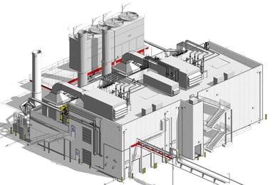
- 17,000 sq ft test facility design for turbofan engine test processes, including R&D, production, and MRO
- 17′ x 18′ hydraulic lift platform for engine access
- Precision thrust frame with load cells for thrust measurement and an integrated calibration system for easy calibration before each test
- Common thrust-frame interface and adjustable access platform to handle a wide range of engine sizes
- 18″ reinforced concrete test cell walls with separated foundations supporting interior support building walls for acoustic isolation
- Bleed air system: Inconel piping, 1200°F operating temperature, 600-700 psi
- Integrated lube and preservation oil support systems
- Integrated fuel delivery system with a simplified process for swapping fuel types
- Infrastructure for future high-voltage DC engine generator systems to feed into the power grid
ACS Services
- Prime contractor/single-source integration project management
- Multi-discipline project coordination
- Mechanical and electrical systems design
- PLC programming and safety interlock systems
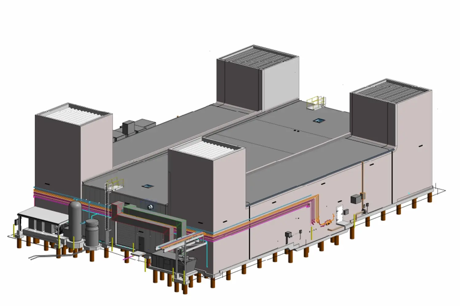
- BIM modeling and spatial coordination
- Construction planning and sequencing